By Erwin Platvoet
The Problem
A refinery heater experienced substantial draft problems resulting in several instances with positive pressure at the arch with excursions of up to 0.25 inH2O (6.3 mmH2O). Adding a steam eductor to the stack is often the simplest solution to create additional draft. Its principle of operation is simple and straightforward: inject steam into the flue gas through one or multiple injection ports and use momentum of the high-velocity steam jets to entrain the surrounding flue gas. However, what is normally a straightforward job became complex due to constraints at site:
- The heater would not be shut down to add a steam eductor or make any modifications.
- There were only two small connections (1½ in. DN40) in the offtakes to the stack that could be used to add lances while the heater is in operation.
- There were no connections on the opposite side of the duct, so the design would only be supported from one side.
- The small diameter lance would need to be robust and resist bending and vibration due to the steam thrust.
- The internal steam velocity could not exceed sonic velocity, and the steam distribution along the length of the lance would need to be uniform.
The Solution
The draft deficiency sets the required amount of steam, which is then used to design a basic steam eductor using empirical formulas for jet pumps. Initial results showed that the internal velocity of the steam lance would approach sonic velocity, and the distribution of steam into flue gas would be challenging. Therefore, CFD modeling was used to design and check the final details of the eductor.
The only way to achieve high steam flow rates with a small diameter lance is by using higher steam pressures. The high ratio of pressures over the injection port results in injection velocities exceeding Mach 4, which creates “barrel shock” regions. To accurately capture high-velocity flow fields inside the lance and across the supersonic regions requires careful meshing and modeling of turbulence.
Figure 1 – Plot of Mach contours at the steam injection port

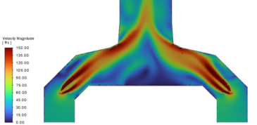
After several iterations, a steam lance design was found that could entrain sufficient flue gas and reduce the inlet static pressure by 0.25 inH2O.
Figure 2 – Velocity contours (ft/s)
To connect to the existing 1.5-inch offtake duct connections without altering the original steelwork, mechanical grip tube fittings and a reducer were utilized in the design. A structural analysis was conducted to verify that the existing connection, shell plate, and nearby stiffeners could safely accommodate the steam thrust forces generated by the lance.
Figure 3 – Steam Lance Fittings

Conclusions
Designing a steam lance can be difficult and requires careful consideration of both the internal and external flow fields, as well as the mechanical robustness. But if the homework is done right, a lance can be designed for the most complicated situations.
Learn more about how our engineering experts can make fired heaters more efficient by reaching out to us at info@xrgtechnologies.com.