As seen in the July 2022 Issue of Hydrocarbon Engineering
Oxides of nitrogen (NOx) are a harmful byproduct of high-temperature combustion used in refining and petrochemical heaters. Refiners and petrochemical producers have made large reductions in the amount of NOx emitted over the last 20 years. Between 2008 and 2017 refineries and chemical producers in the USA have reduced their NOx emissions by 20% (National Emissions Inventory (NEI)). This reduction is in addition to significant reductions made in the previous decades.
When faced with lower environmental targets or increased demand from existing equipment it can be difficult to meet NOx requirements for fired heaters. Increasing the combustion air temperature is one of the most effective ways to reduce carbon dioxide (CO2) emissions, but this, in turn, increases NOx emissions. Modern ultra-low NOx burners often produce more NOx than allowed as the combustion air temperature increases to enable heater efficiencies greater than 90%.
Limitations on peak radiation heat flux often limit heat transfer to the tubes. As the process feed rate to the heater increases, the heat flux must also increase to achieve the desired outlet temperature. If one does not decrease the peak-to-average heat flux ratio the tubes will overheat; the inside convection heat transfer cooling the tube increases proportionally to 0.8 power with flow rate while the outside radiation heat transfer increases linearly.
It is known and is now part of the API 560 standard, that too much heat released with a given cross-section of a fired heater results in low-quality flames that may impinge on the heater tubes. Impinging flame increases the local tube temperature much more than an increase in firing rate. This high temperature can cause coking of petroleum feedstocks, oxidation/carburization of the heater tubes, and may result in mechanical failure of the tube itself.
High-temperature flames produce NOx, increase localized radiation heat flux, and can be carried by furnace currents to impinge on tube surfaces. Low-temperature combustion without flame can eliminate these issues. For example, in 1993 Japan’s New Energy and Industrial Technology Development Center demonstrated highly efficient combustion using 1000°C combustion air temperature while reducing NOx and CO2 emissions (Gyung-Min Choi, 2001).
When properly designed, flameless combustion in a fired heater will reduce NOx, reduce the peak-to-average heat flux ratio, allow for wide fuel gas variability, and enable higher combustion air temperature. However, many practical considerations have inhibited the use of flameless combustion in fired heaters: the substantial number of fired heaters already in service, requirements for flame sensing in those heaters, potential changes in operation, and concerns about unknown interaction between flameless combustion and the heater. A dispersed combustion system, a system that combines flames and flameless operation, practically resolves these issues.
Worldwide Number of Fired Heaters and the State of Technology
The estimated number of fired heaters in refineries and petrochemical plants worldwide is over 10,000. It is not practical or cost-effective to replace these heaters with purpose-built flameless heaters. Any practical solution should be able to be applied to existing assets.
Selective catalytic reduction systems (SCR) reduce NOx but have not been cost-effective for smaller heaters, which represent a large majority of the heaters that have not been already retrofitted for improved NOx performance. In addition to the barrier of cost, there may simply not be space available to place an SCR on a heater. Preheated combustion air typically improves the heat flux uniformity in the radiant section, but only to a limit. To debottleneck a heater and further increase the heater capacity another technology is required.
System Overview
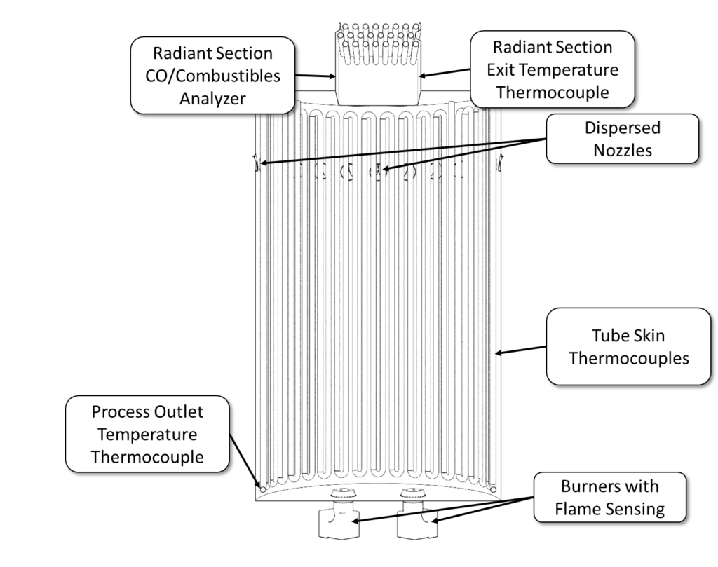
Figure 1 shows an overview of a dispersed combustion system inside a cut-away view of a fired heater. Conventional or ultra-low NOx burners remain in place. The radiant section exit temperature thermocouple is used to measure the temperature of the flue gas exiting the radiant section. Most heaters have a radiant section exit temperature thermocouple. It is increasingly common to find a CO or combustibles analyzer installed, but not all fired heaters have this equipment. Dispersed combustion nozzles are installed some distance away from the burners near the top of the radiant section. Many heaters have tube skin thermocouples used to measure the metal temperature of the process tubes. The process temperature is measured at the exit of the radiant section. Many heaters now have flame sensing, which is typically a UV/IR scanner, built into the burners.
Figure 1 – Overview of a dispersed combustion system and sensors in the radiant section of a fired heater.
The dispersed combustion nozzles are not burners. These nozzles are supplied with fuel that mixes with flue gas both internal to the nozzle and in the radiant section. No fuel is supplied to these nozzles during startup, turndown, or shutdown of the heater. In these states, the heater is instead heated by combustion from the burners alone. There is no change to the current startup, shutdown, or emergency stop procedures.
During normal operation when the temperature at a specified location is greater than the temperature required to completely oxidize the fuel, the nozzles are placed into service, and a large portion of the fuel is diverted from the burners to these nozzles. The fuel gas from these nozzles burns diffusely in the radiant section reducing NOx emissions and the peak-to-average heat flux ratio at the heater tubes. The reduction in NOx means that heaters that are limited in capacity by their air permit limits can increase capacity. The reduction in peak-to-average heat flux to the tube enables increased capacity for heaters that are limited by high tube metal temperature.
All the combustion air always comes through the burners. When fuel is diverted from the dispersed combustion nozzles to the burners, the required combustion air is already present because the flow rate of air has never changed.
Sensing Requirements
Flame Sensing
Flame sensing is required on many fired heaters because of either regulation or local practice. One obstacle to implementing flameless combustion is that there is no flame to sense. While the use of thermocouples, infrared sensors for surface temperature, or flame ionization are all possible technical solutions, their use requires a change in operating practice and control schemes. If instead a baseload of detectable flame from burners remains in the system, then the existing flame sensors can be used to detect flame within the heater. The outlet temperature proves combustion while the use of flame sensors on the burners satisfies regulatory requirements and proves a stable ignition source within the heater.
Temperature Sensing
Combustion is proven using the radiant section outlet and process temperature thermocouples. Only the radiant section outlet temperature is required to prove a temperature rise on the flue-gas side of the heater.
For dispersed combustion, the nozzles may only be operated when radiant section temperature exceeds the required temperature threshold. The importance of this measurement suggests that redundant thermocouples be used with the lowest reading of the thermocouples limiting the operation. Sensing by other means, such as an infrared scanner, would provide yet another measurement of temperature with entirely different failure mechanisms from thermocouples.
Tube skin thermocouples can be used to prove that the dispersed combustion is not pre-igniting near the heater tubes. This is an additional measure to prove the proper operation of the heater. The dispersed combustion nozzles are designed such that no flame can form downstream of the nozzle given the exit velocity and dilution of the fuel.
Carbon Monoxide/Unburned Hydrocarbon Sensing
The use of carbon monoxide or unburned hydrocarbon measurements provides additional proof that the dispersed combustion system is operating as designed. Negligible readings from either indicate that the combustion is being completed in the radiant section
Control Requirements
Typically, the only additional controls required to retrofit a heater for dispersed combustion are valves placed on the fuel gas supply to the dispersed combustion nozzles. To comply with European or Canadian standards several of these nozzles should be placed on the same control valve as a burner with flame sensing. They are removed from service when the burner is shut off. No additional controls are required from the airside of the system because all combustion air flows through the burners.
Hardware Requirements
Burners
Dispersed combustion does not replace burners. The total NOx issuing from the system is a mixture of the NOx produced by the burner flames and the negligible amount of NOx produced by the dispersed combustion from the nozzles. More fuel diverted to the nozzles reduces the NOx in almost direct proportion. However, a heater using dispersed combustion with ultra-low NOx burners will emit less NOx than one with conventional burners. The exact selection of ultra-low NOx burner can further reduce NOx emissions.
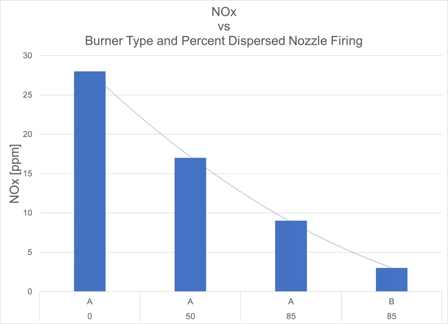
Figure 2 shows NOx predictions from CFD simulations with different burner types and amounts of fuel diverted to the dispersed combustion nozzles. The heater simulated is a forced draft preheated air system. The combustion air temperature is 250°C and the fuel is olefinic. Firing the heater without dispersed combustion using ultra-low NOx burner design ‘A’ results in emissions of 28 ppm NOx. Using the same burner with 50% of the fuel diverted to the dispersed combustion nozzles reduces the NOx emissions to 17 ppm. Further increasing the dispersed combustion fuel to 85% of the duty reduces the NOx to 9 ppm, or near that of an SCR. Holding the dispersed combustion constant at 85% and changing the burner to a second design reduces the NOx to 3 ppm, or less than is required of most SCRs on fired heaters. Dispersed combustion works in concert with the best performing burners to produce the lowest NOx.
Insulation and Refractory
The dispersed combustion nozzles increase the velocity and temperature behind the tubes in a vertical cylindrical heater. For heaters with brick or hard refractory on the shielded walls, it is typical that no changes need to be made. While the temperature between the tubes and the wall increases, the amount of heat supplied in this region does not heat the outer wall beyond the original design limit for most heaters.
For heaters lined with ceramic fiber, the velocity behind the tubes is increased enough that some changes need to be made to prevent erosion. Insulation can be shielded with a metal liner or replaced with hard refractory in the highest velocity areas. In the lower velocity areas, applying a rigidizer will meet most insulation manufacturers’ requirements.
Example Operation: Emergency Stop
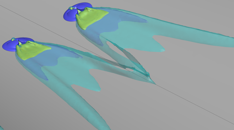
Figure 3 shows frames taken from a transient CFD simulation of an emergency stop in a heater with dispersed combustion active. In this simulation, 40% of the heat release comes from fuel in the burners and 60% comes from the dispersed combustion nozzles. The fuel in question has a lower flammability limit (LFL) of 1.9% by volume in 26°C air. In the images, regions with 1.9% volume fuel or greater are colored yellow.
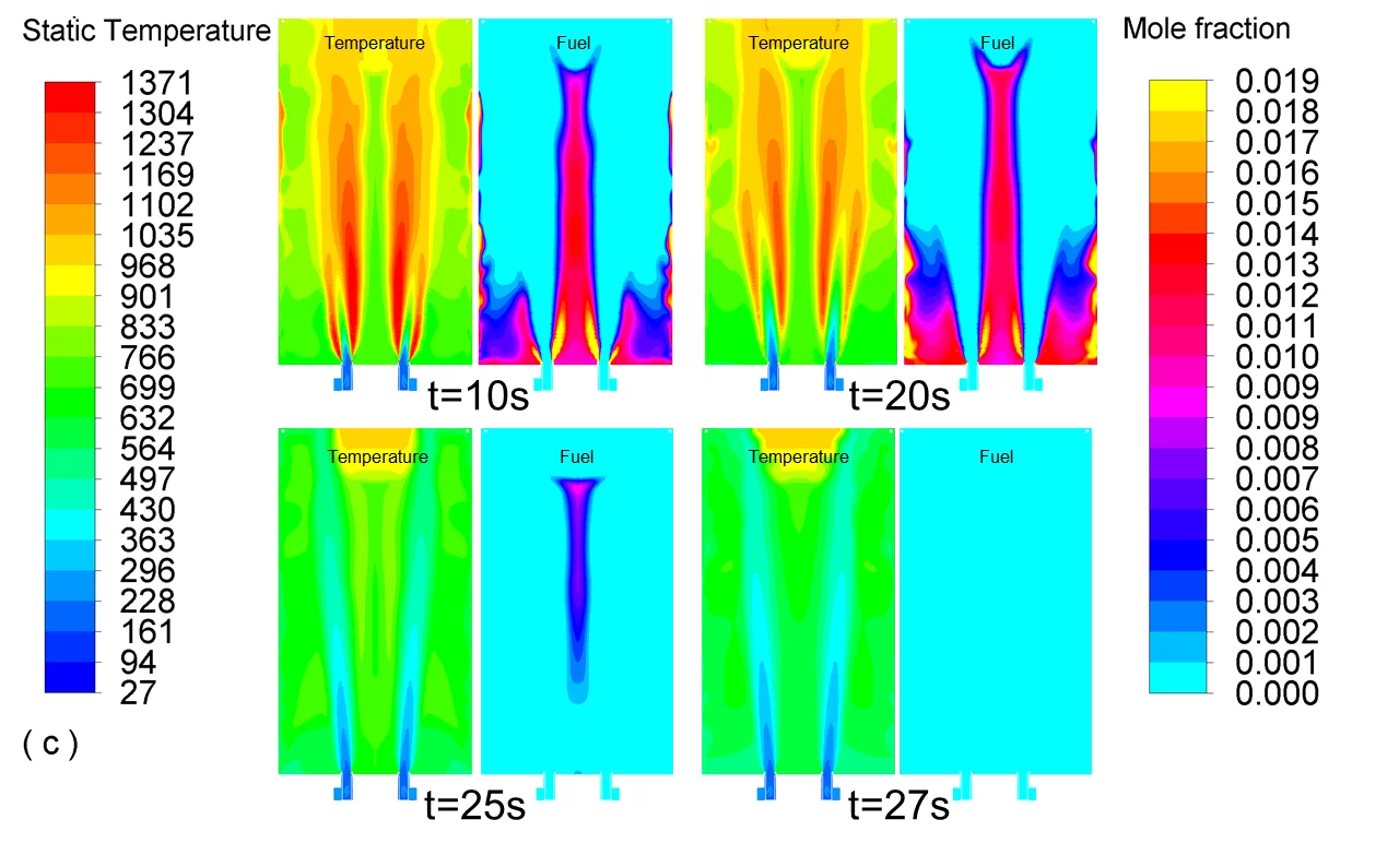
At 10 seconds, combustion is steady in the radiant section. One can see higher temperatures from the secondary stages of the burner flame. Behind the tubes, the flue gas temperature is higher from the dispersed combustion nozzles but not as high as the burner flame temperature. In the plot of the fuel at the same time, the regions of fuel that meet LFL at low temperatures (LFLlow) from the secondary stages of the burners are visible. There is a smaller region of LFLlow behind the tubes. It is noteworthy that there is no temperature rise in these regions behind the tubes; the fuel is being diluted but is not yet fully combusting.
At 20 seconds, the fuel to the burners, the dispersed combustion nozzles, and the pilots is shut off. The combustion air continues to be driven by the fan. The flame has already begun to lift away from the burner tiles in the temperature view. The fuel from the dispersed combustion nozzles is also releasing less heat behind the tubes. In the fuel view, more unburned fuel has been carried toward the bottom of the heater by the circulation pattern of the fuel gas being driven toward the exit of the radiant section.
By 25 seconds all the fuel from the dispersed combustion nozzles has been depleted. Only fuel in the middle of the burner circle remains. The entire radiant section has a fuel concentration below LFLlow. One can see at the top of the radiant section that hot flue gas has been temporarily pulled into the top of the radiant section from the convection section.
Finally, at 27 seconds, the fuel is completely depleted from the radiant section. This occurs before the temperature of the radiant section has reduced below 600°C and within 7 seconds of the emergency stop. Even though 60% of the fuel was being supplied through the dispersed combustion nozzles, the fuel is depleted within less than one volume turnover.
Summary
To meet current and future NOx requirements while allowing for a substantial increase in capacity from existing heaters a cost-effective technology is required. Although technology already exists to reduce NOx and capacity can be increased with a revamp, it is not always cost-effective or practical to implement. Dispersed combustion builds on proven technology to reduce emissions from fired heaters while allowing for increased capacity. With very few changes to the heater controls, hardware, or operating practices this system can be implemented. Even in abnormal conditions, such as an emergency stop, the dispersed combustion system does not change the operating requirements of the heater. Dispersed combustion within a fired heater provides a practical, cost-effective means to reduce emissions and debottleneck heaters.
References
Gyung-Min Choi, M. K. (2001). Advanced low NOx combustion using highly preheated air. Energy Conversion and Management, 639-652.
National Emissions Inventory (NEI). (n.d.). Retrieved 2022, from the United States Environmental Protection Agency: https://www.epa.gov/air-emissions-inventories/national-emissions-inventory-nei
About the Author:
 Matt Martin
As the Lead Scientist at XRG, Matt has over 30 years of experience in the combustion industry. He specializes in CFD of fired equipment, including UOP platforming heaters, burners in process heaters, thermal oxidizers and flares with over 300 simulations of installed, field-proven equipment. Matt received a Bachelor of Science in Computer Science with a minor in Mathematics from the University of Tulsa. He has written numerous publications, is listed as inventor or co-inventor on 27 patents and was awarded the title of Honeywell Fellow in 2011 for technical excellence and leadership.
About XRG Technologies:
XRG Technologies is an innovative engineering and procurement firm specializing in the design and supply of new fired heaters and the optimization of existing combustion equipment. We collaborate with end users in the refining, petrochemical, and power markets.
Our staff of industry experts will partner with you and function as your outside engineering support team. Our team of fired heater, burner, boiler, flare, vapor recovery and thermal oxidizer experts create one centralized, go-to engineering firm for all your fired equipment needs!