Article by: Zac Pivarnik, P.E., Mechanical Design Engineer
When you design a steel member for bending stresses, do you go straight to an elastic bending calculation without any further thought? Time to level up! Let me show you why you may be over designing your industrial structures, including fired heaters.
Steel is the go-to material for designing buildings, pressure vessels, fired heaters, and other industrial structures. It’s strong, ductile, and easy to customize. But when it comes to designing structural steel members, there’s a lot to consider, especially when it comes to bending stresses in beams. Structural engineers typically use the plastic moment capacity for structural steel, but engineers who aren’t familiar with structural engineering theory or aren’t using AISC specifications often use the more conservative elastic bending capacity. This is understandable, but it can lead to unnecessarily expensive designs. In this blog post, I’m going to explain the difference between plastic and elastic bending, and I’ll specify the minimum requirements for when it is acceptable to use the extra capacity provided by the plastic section modulus. Why does this matter? Well, because using the plastic section modulus can save you a lot of money on your refinery structures or buildings.
Plastic vs. Elastic Section Modulus
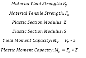
Section modulus is a useful beam property in structural engineering because it combines the relevant section properties needed to calculate bending stresses on a beam. The section modulus determines the maximum point at which a beam can bend without yielding or breaking.
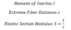
The elastic section modulus is the ratio of the second area of moment, also called the moment of inertia, to the distance from the neutral axis to any given fiber in the section. The elastic neutral axis (ENA) of a cross section lies at its centroid. Elastic bending assumes that the member has not reached its maximum yield moment and it acts as a linearly elastic material. Hence, it experiences no elastic yielding.
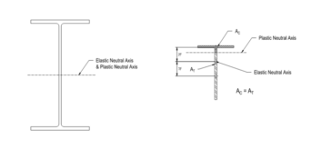
The plastic section modulus is dependent on the plastic neutral axis (PNA), which is the location that splits the cross section such that the compression and tension forces are equal over the compression area and tension area. For sections with constant yielding stress, like a steel shape, the area above and below the plastic neutral axis is equal. Note that for a symmetrical shape, the PNA and ENA will be at the center of gravity of the shape. For an asymmetrical shape, the PNA and ENA will be different. See Figure 1 below for an example of the PNA location for an asymmetrical shape. Using the plastic moment as the limit of bending strength assumes that some elastic yielding is acceptable.

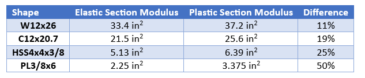
Using the plastic section modulus and plastic moment for flexural capacity results in approximately 10% more capacity than using the elastic section modulus and yield moment for W shapes and channels. When considering other shapes like rectangular plates, the difference in strength can be much more drastic, resulting in a 50% difference. That amount of weight can add up and result in significantly overdesigned members. See Table 1 for some common shape examples and the differences between their strong axis section moduli which directly determine their bending capacities.
The Case for Plastic Moment Capacity in Member Design
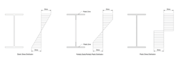
Using the plastic moment capacity might raise eyebrows for some engineers who, accustomed to avoiding plastic design, associate it with high seismic applications outlined in AISC standards. Plastic deformation is permanent and therefore plastic bending should be avoided right? Using the plastic moment capacity in the right situations is safe and a tried-and-true practice in the structural steel building industry. A beam’s plastic moment is the theoretical limit where the entire section has yielded, and if any more load is applied a plastic hinge will form in the member. The plastic moment limit precludes the plastic hinge completely forming, and part of the section still has not yielded. Designing a beam capacity at its plastic moment with a safety factor will keep it in a partially plastic/partially elastic state as shown in figure 2 and will not allow the full section to go into fully plastic bending and start significant permanent deformation in the member.
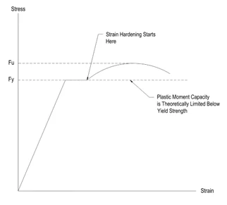
In the partially plastic/partially elastic state, the material’s stress is not increasing with an increase of load. Instead, the material is experiencing strain hardening to redistribute stress to the unyielded areas of the cross section. Strain hardening is nothing to be afraid of. In fact, it makes the steel stronger and raises the yield strength of the material! Steel’s ductility or the ability to experience strain hardening is the reason it’s used widely for large structures. Ignoring steel’s ability to plasticly bend ignores how structures will realistically behave.
Furthermore, the yield strength is used to calculate the plastic moment in lieu of the ultimate strength, even though theoretically the actual maximum plastic strength is at the ultimate strength limit. By limiting the material to the yield strength, we stay well away from any sudden fracture and add a little more cushion to our safety factor. Stepping away from theory and into practical experience, we need to define when it’s acceptable to leverage the plastic moment capacity in our steel structure and fired heater designs.
When is it Acceptable to Use the Plastic Section Modulus for Bending Stresses?
- The steel member must be a compact section as described per AISC Specification Table B4.1b. AISC specifies minimum width-thickness ratios for the webs and flanges of members. Cross sections with large width-thickness ratios are more susceptible to local buckling. These members are more likely to fail due to buckling before they can reach their plastic moment capacity.
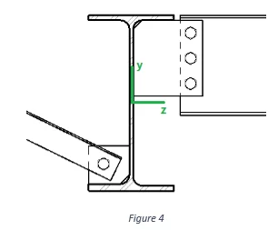
- The unbraced length of the member must be adequate to develop the plastic moment without any buckling limit states failing first. See figure 3 for an example of a beam that has its compression flange braced for lateral-torsional buckling.
- Small deformations under yielding must be acceptable. Designing for an elastic bending condition will limit deformation and deflection more than when designing for the plastic moment. However, in most structural cases the differences in deflection are small and, in any case where deflection is a major concern, a detailed deflection analysis should be performed to determine the required member size.
- The material must be ductile, like typical mild structural steels. A brittle material cannot withstand significant deformation after its yield point and would fracture before it reaches a plastic state.
- The environment around the structure should be at a reasonably typical temperature. In extremely high and low temperatures, ductility can be affected. While higher temperatures can increase ductility, the relationship between ductility and temperature is not always linear and ductility can peak and decrease at extremely high temperatures. In fact, even elastic bending design is not sufficient at high temperatures where creep design is typically the governing factor. Therefore, the plastic bending capacity should not be used on any steel inside a fired heater where temperatures can exceed 2000 °F.
- The loads on the member or structure should be static and not include any cyclical fatigue loads. Through ductility and plastic deformation, stress concentrations are typically smoothed out in plastic bending under a static load. However, the elimination of stress risers does not happen until the required amount of plastic deformation takes place to redistribute the stress. Under cyclical working loads, there can be significant stress concentrations before any stress redistribution takes place, and a plastic analysis would not accurately reflect this.
Conclusion
Comprehending the plasticity of steel and its capacity to endure stresses surpassing the yield strength is a pivotal concept for both structural and mechanical engineers. Designing steel members to an elastic yielding limit state will consistently result in overdesigned members and higher costs for your customers and clients. While the AISC Specification for Structural Steel Buildings may not align perfectly with the specifics of every project, it serves as a baseline to get greater capacity from fired heaters and other engineered steel structures safely. It is the individual engineer’s responsibility to determine what assumptions and calculation methods are adequate for a specific design. For economic efficiency, the plastic moment capacity needs consideration when designing for bending stresses in steel members.
Please keep in mind that the elastic or plastic bending is not the only limit state that needs to be checked on a member experiencing bending. All applicable local buckling limit states should be checked as well. Reference the most up to date AISC Specification for Structural Steel Buildings and the Companion to the AISC Steel Construction Manual Design Examples for a more detailed explanation of flexural steel calculations.