By Erwin Platvoet, Chief Technology Officer
Part 3 up next: Burner fouling!
If you didn’t read Part 1 on Interior Fouling, catch up here!
Exterior Fouling of Radiant Process Tubes
An important fouling mechanism on the fireside is corrosion fouling, especially for oil fired equipment. The bad actors are compounds of sulfur, vanadium, and sodium. In fired process heaters the main problem is hot fuel ash corrosion that occurs when firing heavy fuel oil.
Hot Fuel Ash Corrosion
Hot fuel ash corrosion is an accelerated form of corrosion in which molten sulfate salts form a film that destroys the normal protective oxide layer. Problems occur with fuel oil that contain sodium and/or vanadium and sulfur (0.6 – 3.6 wt%). Salts like Na2SO4 form at high temperature and condense on the tubes, causing rapid metal consumption at about 550° C. Reducing conditions exacerbates fuel-ash corrosion. The presence of carbon monoxide and/or unburned carbon and hydrogen sulfide promote the formation of metallic sulfides. Iron sulfide, for example, is less protective than iron oxide. Sulfides tend to be less protective because they are porous and less firmly attached to the steel.

Figure 1 – Hot fuel ash deposition and corrosion
Corrosion rates can be exceedingly high. In boilers, where this type of corrosion is more common, carbon steel wastage rates of about 1/2 inch per year (failure in less than 2,000 hours of operation are documented by the NBBI.
Source: https://www.nationalboard.org/index.aspx?pageID=164&ID=196
High Temperature Oxidation

High temperature oxidation is a corrosion process mostly associated with CS or low alloy tubes. These tube materials oxidize at temperatures within creep/rupture limits. Reasons for overheating include flame impingement, overfiring of the heater, or incorrect selection of tube metallurgy for the service. The resulting oxidation layer (“scale”) results in tube wall thinning and can reduce the local absorbed heat flux by half.
- the lower emissivity of the scale reduces the radiant absorbed heat flux
- the thermal conductivity of the scale is of the same order of magnitude as coke and therefore has a comparable effect on overall thermal resistance
- problems compound exponentially if the oxide layer loses contact with the tube and further reduces any heat transfer by convection, conduction, or radiation. The loss of radiant section efficiency can be substantial, which is particularly an issue in heaters where the primary process is only in the radiant section
Each cycle of scale formation and removal reduces the tube wall thickness until the tube is too thin to contain the fluid pressure and failure occurs. This issue can be detected several ways:
- visual tube inspection during outage. When inspecting the radiant tubes, metal oxides are sometimes confused with combustion deposits. Since oxide scales are magnetic, they can be distinguished from combustion deposits with a magnet
- IR thermography when the heater is in operation. IR can be used to compose a tube temperature map, where areas of high temperature can be the result of internal/external fouling, an oxidation layer or a combination of these. Areas with oxidation typically are found to have sharp edges revealing that layers have grown and spalled off, leaving a step change in thickness. Areas with internal coking tend not to have sharp transitions
- CFD can model the temperature patterns inside the heater and demonstrate high local fluxes resulting in high metal and film temperature
- Skin thermocouples can detect a fouling problem if they are installed in the correct location. Even then, it is difficult to differentiate between scaling, flame impingement, and internal fouling. Scaling can be a very local problem depending on the cause of high temperatures

Figure 2 – heat and flame patterns predicted by CFD (left) and actual operation (right)
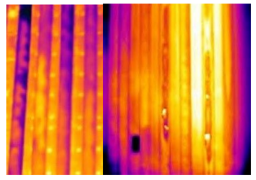
Figure 3 – IR maps of radiant coil

Figure 4 – Scale on radiant tube
Source: https://integratedglobal.com/industries/oil-gas/cru-catalytic-reformer-heaters
Mitigation / Prevention
High temperature oxidation can be prevented by reducing hot spots on the coils. Flame interactions that result in impingement and hot spots on tubes can be prevented by changing burner design / layout inside the firebox or with XRG’s latest patented technology, Xceed.
Tube metallurgy can be upgraded to higher chrome and nickel alloys to better withstand high temperature oxidation. While a chromium-rich oxide layer mainly accounts for the corrosion resistance of stainless steels, the addition of nickel improves creep resistance of austenitic steels. Nickel also promotes stability of the protective oxide film and reduces spalling during thermal cycling.
While cleaning tubes during outages is easiest and most effective, severe scaling and fouling may have to be removed during furnace operation. Specialized companies developed methods to clean radiant tubes, as shown in Figure 5. Efficacy is a function of the ability to get a lance within a couple feet of the area to be cleaned. It should not be used where ceramic fiber is the refractory behind the tubes. In addition to online chemical blasting, walnut shell blasting can remove loose scale from the tubes. Neither method is effective at removing scale tightly adhered to the tubes.

Figure 5 – Online chemical blasting of radiant tubes. Source: Furnace Solutions
Ceramic coatings can be applied to the exterior surface of tubes to delay onset and reduce oxidation rate. For example, Cetek Ceramic Coatings provide a durable, protective, thin-film layer on the surfaces of process tubes which resist oxidation and corrosion of the metal and maintains the tube thermal conductivity coefficient and emissivity close to new tube conditions. Having uniform tube OD surface conditions also makes interpretation of IR thermography easier.
Convection Fouling
To maximize the heat transfer in the convection bank, tubes are fitted with radial fins up to 1 inch high, spaced at maximum 5 fins per inch. The dense spacing makes the fins great trapping sites for refractory fiber, ash from oil combustion, dust, and sand. Other potential sources for convection fouling are:
- Deposits of silica that volatilized from radiant section walls. This is typically limited to applications with ceramic fiber walls and wall-fired burners.
- Tubes with fin tips that experience high oxidation rates.
- Operating with tube skin temperatures below the sulfuric acid dew point. This creates a damp surface that can catch any fibers or particulate.

Figure 6 – Fouled fins
Even with a small layer of deposits, heat transfer efficiency is severely reduced.
Convection section fouling manifests itself as high convection pressure drop due to the accumulation of fouling on the fins. The heater can become draft limited when the convection section pressure drop exceeds the draft capacity of the stack, resulting in low firebox oxygen. It also lowers the process crossover temperature and increases the flue gas stack temperature due to the loss of heat transfer in the convection section.
The risks of excessive convection fouling are:
- Low heater efficiency, high fuel consumption
- Running the burners out of oxygen
- Accumulation of unburned hydrocarbons in the firebox
- Increased flue gas temperature which can overheat tube supports, fins, and downstream components not rated for high temperatures
- Heater throughput becomes limited
- Exceeding stack temperature limit
Convection Bank Cleaning
There are various methods available to clean the convection bank tubes, but their efficiencies depend on the ability to reach every part of the fouled surface.

Figure 7 – Convection tubes before and after cleaning
Water Wash
Water washing can damage refractory and produce cement like fouling deposits on and between fins. Tarp systems are required to catch the water. Cleaning progress can be monitored by visual inspection of the finned tubes and sampling the wastewater by checking its color after each cycle. Detergent can be added to improve cleaning efficiency.

Figure 8 – Convection section water wash
CO2 (Dry Ice) Pellets
For efficient contamination removal, the system shoots small dry ice pieces at the cleaning target. This system is designed to clean by applying thermo-mechanical impact shock. This is typically performed while in service. Lances are inserted through ports in the sidewall. A well-planned port size and layout is critical to proper coverage with a lance.
Grit Blasting
Like water washing, this requires collection and disposal. Abrasive methods can damage fins and refractory.
Robotic Cleaning
Self-propelled robots move along the tubes to clean the surface.
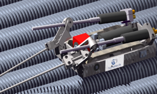
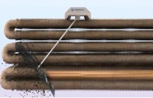
Figure 9 – Robotic cleaning. Source: www.TubeTech.com
Soot Blowers
Fixed or retractable system of lances that periodically clean the tubes by injecting steam or high-pressure air from opposing rotating nozzles while the furnace remains online. Typically, soot blowing is only effective on softer types of fouling (like soot).
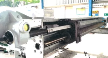
Figure 10- Soot blower module
The appropriate cleaning method should be selected based on these considerations:
- Access – to allow proper access to the tubes, provide cleaning lanes in the convection section. The cleaning lane should be at least 2 ft. high. The maximum vertical coverage of a lane should not exceed three tube rows. They must cover all rows, including shield and future rows.
- Efficacy / Time – while online sootblowers require much less time than off-line cleaning methods, they are not nearly as capable of removing anything other than soft fouling like ash and soot.
- Disposal – compared to water washing and sand blasting, soot blowing and dry ice pellets do not require tarps to catch and dispose of the effluents.
- Erosion – abrasive cleaning methods such as dry ice and grit blasting may damage refractory and fins. Robotic cleaning uses water pressure of several thousand psi. This can also damage fins, albeit to a lesser extent. It is more controlled than water washing and less prone to damaging refractory.
- Safety – some users are concerned about accumulation of CO2 and asphyxiation risks when dry ice pellets are used during a turnaround.
- Cost – while it is the most efficient, robotic cleaning is often the most expensive cleaning method.
Sulfuric Acid Corrosion
Sulfuric acid condensation is another source of potential convection fouling and corrosion. Sulfur in the fuel forms sulfur oxides in the flame. For example, dihydrogen sulfide reacts with oxygen to form sulfur dioxide:
H2S + 1.5 O2 -> SO2 + H2O
The sulfur dioxide then reacts with excess oxygen to make sulfur trioxide:
SO2 + 0.5 O2 <- -> SO3
The SO3 then condenses as sulfuric acid:
SO3 + H2O ->H2SO4
Even at low sulfur concentrations, the sulfuric acid dewpoint is well over 110°C / 230°F:

Figure 11 – Relationship between sulfur content and acid dewpoint. Source: API 560 – Annex
The effects of sulfuric acid corrosion can be dramatic:


Figure 12
Disposal of the cleaning effluent is another problem since water washing can result in a strong sulfuric acid.
Studded tubes are used in applications that require frequent cleaning, such as oil firing. They are more resistant to corrosion from contaminants like sulfuric acid. While they are more resistant to aggressive and frequent cleaning methods, opinions differ as to whether they are easier to clean than solid fins when the studs are staggered.

Figure 13 – Fouling in studded tubes
SCR / APH Fouling
The deNOx reactor and air preheater (APH) are located downstream of the convection section and suffer from the same types of fouling as the finned tubes, like particle deposition of ash, soot, refractory fibers, and dust. In addition, the APH can also suffer from sulfuric acid condensation, corrosion, and fouling by ammonia salts.
Since the air preheater is usually much cooler than the convection tubes, fouling caused by sulfuric acid condensation and corrosion is a bigger problem. It is challenging to design a system with the heat exchange surface well above the acid dewpoint (ADP) for all operating conditions. The problem can be severe in plate type exchangers where plate thickness of older units ranges from 1 – 2 mm, and corrosion quickly leads to holes and leakage between the air and flue gas side. Newer units have thicker cold ends (5-6 mm), providing extra corrosion allowance.
It is important to monitor the cold corners using thermocouples or IR cameras. Use cold air bypassing or hot air recirculation to maintain the cold corner above the ADP. If steam or boiler feed water is available, a small heat exchanger (‘calorifier’) can preheat the air before entering the APH.

Figure 14 – Sulfuric acid corrosion in plate type APH
If an SCR is used to reduce the NOx in the flue gas, fouling may occur. Sulfur in the fuel is converted to ammonia salts as follows:
First, SO2 to SO3 conversion is catalyzed by V2O5 catalyst. We know that SO3 reacts with H2O to form the sulfuric acid and sulfur trioxide reacts with ammonia to form ammonium salts.
Ammonium sulphate is a powdery substance:
2NH3 + SO3 + H2O <-> (NH4)2SO4 (s)
Ammonium bisulphate is sticky and hard to remove. The salts are water soluble, so it is common practice to bypass the SCR/APH circuit for water washing when fouling becomes intolerable. Sublimation can also remove the salts but is practiced less frequently as the resulting plume is unacceptable is some regions.
NH3 + SO3 + H2O <–> NH4HSO4 (l)
The rate of salt formation depends on the SO3 concentration, ammonia concentration (slip), and flue gas temperature. The formation rate becomes very significant below 500°F.
Risks & Mitigation
The fouling results in SCR catalyst masking and eventual deactivation if the flue gas is below 450-500°F. Most systems are designed to automatically stop NH3 flow if flue gas to the SCR hits ~450°F.
ABS salts foul downstream equipment like air preheaters. Periodic cleaning with water is the typical way to address salt accumulation. The effluent may contain sulfuric acid and ammonia which requires wastewater treatment.
Since formation rate depends on the flue gas composition and temperature, it may be extremely difficult to control in cycling services.
It is important to monitor the ammonia slip and keep it as low as possible. Monitor the APH metal temperature in the coldest corner and maintain it well above the ADP. Use cold air bypass, preheat combustion air with an external fluid, or recirculate hot air.

Figure 15 – Fouling by ammonia salts
Conclusion
Exterior fouling of the radiant process tubes, convection section, and the SCR/APH can wreak havoc on your heaters. When developing a strategy to address fouling, it is critical to consider corrosion, effectiveness, and long-term damage to materials inside the heater.
Reach out to us with fouling related questions at info@xrgtechnologies.com