Featured in Hydrocarbon Processing, January 2022 Issue
By Erwin Platvoet, XRG Technologies
Introduction
Fired heaters are facing scrutiny because they contribute to the global emissions of carbon dioxide (CO2) and nitrogen oxides (NOx). For refineries and petrochemical plants focused on reducing greenhouse gas emissions, it makes sense to target CO2 from fired heaters since they usually have a fuel efficiency between 70-90% and are a major contributor of the site’s overall emission production. However, revamping fired heaters only to reduce emissions, whether for NOx or CO2, is unattractive for operators, since it would not generate additional value. A revamp that improves heater capacity, reliability, and availability creates much more value. Revamping a fired heater can be a complex task, especially when dealing with multiple problems simultaneously. A structured methodology is required to successfully determine what problems need to be resolved, in what priority, and what decisions must be made to find the best possible solution.
An example of a successful revamp using this methodology will be used to demonstrate that the goal of emissions reductions can be achieved while improving the bottom line.
Elements of a successful revamp
The Kepner-Tregoe Matrix is ideal for analyzing a complex revamp and consists of four steps:
- Situational Analysis – a high-level definition of the concerns to address
- Problem Analysis – narrowing in on the specifics and determine root causes
- Decision Analysis – collect and evaluate alternatives on the merits and risks, decide which option is the best possible choice
- Potential Problem Analysis – a preventative step to evaluate the impact of the decisions on the system and avoid new problems
This approach is demonstrated for a recent retrofit of a vertical cylindrical heater by XRG Technologies.
Situation Analysis
The situation analysis is usually performed by the owner/operator. In the case of our example, the high-level issue for the owner was the heater capacity. A plant study showed that the output could be increased by 20 – 30% if the crude heater could be debottlenecked. However, secondary issues also had to be resolved before a capacity increase could even be considered. The most obvious was that many radiant tubes showed damage such as high-temperature oxidation, tube wall thinning, and creep. Another concern was the short time between decoke cycles, indicative of a potentially high coking rate. Any solutions needed to consider stringent NOx emission limits as well as high CO2 taxes that would be imposed after the year 2020.
Problem Analysis
Fired heaters are complex pieces of equipment that can be difficult to analyze. The key to a successful retrofit starts with an engineering study to understand all aspects of the heater. Most heater studies begin with a survey in the field to record the present mechanical condition of the heater, observe the flames, measure stack emissions, and collect operating data. This is also an excellent opportunity to interview operators about difficulties they experience controlling the heater. This information is used to generate thermohydraulic models to identify bottlenecks in the present or future operation. Comparing the model results with actual operating data can reveal issues that are not readily observed, like fouling inside the tubes or loss of heat transfer in the convection section.
Key findings of the survey of the VC heater were:
- Temperature/heat flux maldistribution. The peak skin temperature difference between the hottest and coldest pass was approximately 50°C (90°F) at Start of Run (SOR). This imbalance increased to about 150°C (270°F) at End of Run (EOR).
- Short runlength. The radiant tube skin temperatures increased by ~120°C (216°F) in only three months.
- Low fuel efficiency. The field data indicated an efficiency between 78 and 79%, despite good mechanical condition of the heater and efficient operation of the burners.
- Loss of heat transfer. Comparison with the thermal models showed that the actual fuel efficiency at SOR (i.e., in clean condition) should have been 2% higher.
Visual observation of the firebox showed flame interactions. Flame interactions almost always result in a performance penalty. Flames rolling into tubes cause hotspots, excessive coke formation, oxidation and tube damage from oxidation, creep, and carburization. Unruly flames are a safety concern, produce high emissions, and shorten the life of many components.
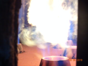
Figure 1 – Rolling flames
The root cause of the flame interactions was investigated by a CFD analysis of the heater. CFD (Computational Fluid Dynamics) is a common tool to evaluate the performance before and after a fired heater revamp.

Figure 2 – Temperature contours on the center plane of the VC heater
In the original design of the firebox, the natural draft burners were arranged in two circles. The outer ring consisted of ten burners while the inner ring consisted of five burners. This layout caused poor flue gas recirculation patterns and flames coalescing in an unsteady flame cloud. Additionally, the outer burners were too close to the radiant tubes causing flames to locally impinge, creating hotspots. The CFD model replicated the poor flame patterns and explained the difference in coil temperatures, high coking rates, and tube degradation issues.
Decision Analysis
Armed with information from an engineering study and CFD analysis, the contractor and the operator jointly evaluate the potential revamp opportunities to reach an achievable and optimal retrofit target. For a heater revamp, these include (but are not limited to):
- Improve safety, reliability, operability
- Eliminate flame interaction problems
- Simplify burner control
- Eliminate ambient effects (e.g., wind, rain)
- Reduce Operating Costs
- Increase fuel efficiency
- Reduce fouling in tubes
- Increase profitability
- Increase capacity and throughput
- Switch to more economic fuels or feedstocks
- Reduce emissions
- Nitrogen oxides (NOx)
- Greenhouse gases (CO2)
- Unburned hydrocarbons (CO, CxHy)
Ideally, several scenarios are developed including estimates for CAPEX and OPEX, while considering credits or penalties for CO2 emissions. For this example, the following four solutions were considered:
| Change existing burner layout | Convection replacement | FD APH | Do nothing | |
| Flame interaction | + | 0 | +++ | — |
| Simplify operation | 0 | 0 | ++ | 0 |
| Eliminate ambient effects | 0 | 0 | +++ | 0 |
| Increase fuel efficiency | 0 | ++ | +++ | 0 |
| Reduce fouling | ++ | ++ | +++ | – |
| Increase capacity | + | ++ | +++ | – |
| Reduce emissions | + | + | + | 0 |
| CAPEX | – | — | — | 0 |
| OPEX | 0 | +++ | ++ | 0 |
| Implementation time | – | — | – | 0 |
Option 1 – Change Existing Burner Layout
Since flame impingement is an important factor in operational and reliability issues of the heater, XRG investigated whether moving the natural draft burners to a single burner circle would improve the overall flame performance. This optimization can be difficult since moving the burners farther from the radiant coils puts them closer together, which increases the risk of flame-flame interactions. Several CFD iterations were used to determine the optimal burner circle diameter. In this scenario, some interactions are still apparent, causing the flames to lean slightly to the center. Nonetheless, the new layout produced an acceptable flame pattern and flux profile. The improved flux profile resulted in improved heat flux and temperature uniformity, allowing the heater to operate at greater capacity. Since neither the burner liberation rate nor the heater surface area is increased, this capacity increase is very limited. Absence of flame interactions will reduce NOx emissions. This solution requires a new heater floor.

Figure 3 – streamlines of the optimized burner circle with 15 burners
Option 2 – Convection Replacement
Replacing the damaged/fouled convection section with a new and more efficient version would increase the fuel efficiency by several percentage points. However, with a feed inlet temperature range of 170 – 200°C (338 – 392°F) the minimum achievable stack temperature is around 250°C (482°F), which limits the fuel efficiency to a maximum of 86%. The 8% gain could lower fuel consumption and CO2 emissions or increase the heater capacity. This option does not address the flame interference problems, so it also requires Option 1 or 3 to de-constrain the firebox operation.
Option 3 – Forced Draft Air Preheat (FDAPH)
The stack temperature of a heater with 78% fuel efficiency is around 400°C (750°F). This heat can be used to heat the combustion air to 300 – 350°C (572 – 662°F). More heat can be extracted from the flue gas than in Option 2, pushing fuel efficiency over 90%. The maximum efficiency is only limited by the dewpoint of sulfuric acid in the APH, which in this case restricts the stack temperature to a minimum of 165°C (329°F).
In this case, the burners must be replaced with forced draft type burners, which have a few advantages:
- The burner capacity can be drastically increased, which allows the number of burners to be reduced from fifteen to five. This allowed use of the inner burner circle without making major modifications to the heater floor other than plugging the outer ring of burners.
- The high air side pressure drop of FD burners results in a more compact and robust flame, which provides more freedom in locating them without causing flame interaction problems.
- Forced draft (FD) burners are not individually controlled by air dampers, but by the FD fan damper or variable speed motor, which simplifies the operator’s job.
- Forced draft burners are not sensitive to ambient effects like wind or rain, which reduces the variability in firebox draft and oxygen. This allows the heater to be operated more consistently and on less excess air, which further improves the system efficiency.
The scope of this option is more substantial than the others, resulting in the highest overall CAPEX:
- New FD burners and pilots
- Fuel piping
- Flue gas/air exchangers
- FD and ID fans with variable speed drives
- Flue gas and air ducting with structural support
- New transition duct and bypass dampers
Decision
While Option 2 (convection replacement) showed the quickest payback time, it only made sense in combination with Option 1 or Option 3 which reduced the economic feasibility. Also, the combination of Option 1 and 3 would not allow for the capacity increase that the customer desired.
Option 3 showed the biggest benefits and the most attractive economics. Purely based on fuel savings and CO2 tax avoidance, the project showed a payback period of less than two years. Most importantly, this option allowed for the highest capacity increase (29%). One benefit of this option was that a large portion of the work could be done with the heater in operation, reducing downtime.
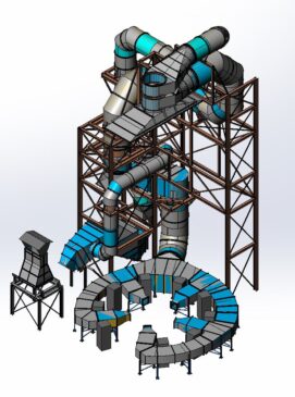
Figure 4 – Overview of revamp scope
Potential Problem Analysis
A drastic modification like this can result in unforeseen issues. An important one could occur during the change of the combustion system and air supply, where potential issues are:
- Flame shape, flame interactions, NOx emissions, incident radiant flux profile, and temperature uniformity using five high capacity FDAPH burners
- Air distribution inside the new combustion air duct
- APH bypass duct design to prevent acid dewpoint corrosion
To mitigate the impact on NOx and ensure the best possible flame performance, Broken Arrow-based company, Zeeco designed the burners. They selected the GLSF FREE JET Round Flame Burner for its compact design and its ability to produce very low NOx emissions while meeting the flux profile requirements for this project for a wide fuel composition ranging from natural gas to LPG. Despite the much higher heat release and air temperature, the GLSF fit in the existing openings of the ND burner, so no floor modifications were necessary. A CFD model of the new arrangement demonstrated that flame impingement would be eliminated with the proposed arrangement while meeting the NOx requirements.
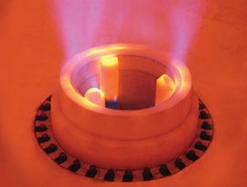
Figure 5 – Zeeco GLSF FREE JET round flame burner
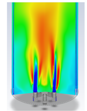
Figure 6 – Temperature contours with five FD burners
On the execution side, a risk that had to be mitigated was potential interference of the large APH structure with the existing equipment. The heater and its surrounding area were scanned using lasers, which produced a 3D model that was imported into the XRG model. During construction, the distance between the new and existing equipment was as small as ½ inch. Thanks to the laser scan technology and 3D modeling, zero field interferences or fit up issues were experienced.
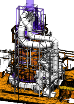
Figure 7 – Model from laser scan (shown as mesh) integrated with new equipment (shown in grey)
Results
The project was successfully executed turnkey within seven months from placement of purchase order to startup. By following a structured decision methodology like the Kepner-Tregoe Matrix, the optimal solution was selected considering CAPEX, OPEX, process availability, reliability, and plant throughput. Integration of smart tools like Computation Fluid Dynamics and 3D modeling in every facet of the design process prevents mistakes and rework while ensuring the project goals are met. The GLSF FREE JET burners produce well-behaved flames without visible interactions. Due to the solid improvement in heat flux uniformity, the coil outlet temperatures are now within a narrow band. The fuel efficiency and capacity goals were met while peak skin temperatures at SOR were 100°C (180°F) lower than before the revamp. The predicted NOx emissions from the CFD model were validated with official stack measurements which showed that the actual emissions were 30% below the required limits.
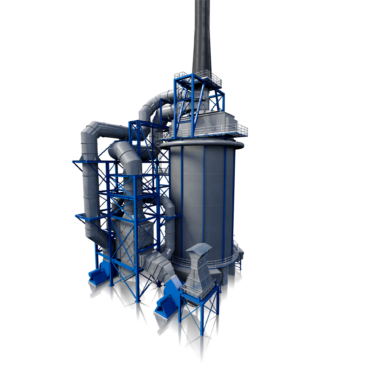
Figure 8 – Model of revamped heater
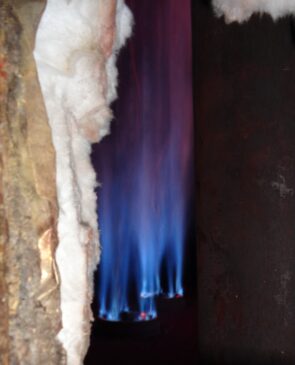
Figure 9 – Flames after revamp
XRG Technologies is an innovative engineering and procurement firm specializing in fired equipment for the refining, petrochemical, and power markets. We collaborate with our partners to solve complex problems and manage projects from concept to completion.
Zeeco is a global leader in the design, engineering and manufacture of next-generation combustion equipment and advanced environmental systems. Our equipment plays mission-critical roles in the refining, production, power, LNG, biogas, pharmaceutical, pulp and paper, and numerous other industries around the world.
Learn more about XRG’s fired heater revamp capabilities here!