By Matthew Martin, XRG Technologies
Introduction
Fired heaters, also called furnaces, use the heat from combustion of hydrocarbons to increase the temperature of a fluid. Direct-fired heaters are common in refining and petrochemicals. In these heaters, flames produced by burners directly irradiate a series of tubes called a coil, which carries the fluid to be heated. Depending on the design and operation, these heaters vary in fuel efficiency from approximately 50% to 95%. A low fuel efficiency causes unnecessary waste of fuel and high carbon dioxide emissions (CO2).
The fuel efficiency of fired heaters can be increased by preheating the air used for combustion. Increased combustion air temperature reduces CO2 but also increases oxides of nitrogen (NOx). NOx causes smog, acid rain and ground-level ozone that damages ecosystems. NOx emissions can be greatly reduced by Selective Catalytic Reduction (SCR) which reacts NOx with ammonia (NH3). SCRs may be costly to install, particularly where there is no ammonia infrastructure in place, and they only address NOx emissions from fired heaters.
Many heaters are operating at a higher capacity than the original design which may result in unacceptably high tube metal temperatures leading to thermal degradation of the process fluid, fouling of the tubes reducing the heat transfer, and potentially a rupture of the tube itself. Additionally, greater heat input often results in higher temperatures everywhere leading to additional stress on other components of the heater such as tube supports.
Changing the fuel from those with higher carbon-to-heat content ratios to those with lower carbon-to-heat content ratios will reduce CO2 emissions. Switching to inorganic fuels, such as hydrogen or ammonia, can eliminate CO2 emissions from the heater stack. However, both of these fuels will change the heat transfer characteristics of the heater, increase NOx emissions, and have other potentially negative effects on heater components.
An ideal solution would increase efficiency, reduce NOx emissions, allow for fuel flexibility, and increase capacity. This solution should also use less space and not require ammonia for NOx reduction. An integrated system for mixing and dispersing fuel within the fired heater can deliver these results.
Heat Transfer in Fired Heaters
Heaters are designed with component sections based on the principal mode of heat transfer from the flue gas to the coil. There are a wide variety of shapes for fired heaters and burners can be placed in the floor, walls, or roof. Figure 1 shows a schematic view of a common fired heater known as a vertical cylindrical. In this design, the process fluid flows from the top of the heater to the bottom, while the combustion products flow from the bottom of the heater to the top.

Figure 1 – Schematic view of a fired heater.
The process first passes through the convection section. Both the process fluid and the flue gas are at the lowest temperature while in this section. The primary mode of heat transfer within the convection section is convective. Attaching fins or studs to the tubes in this section will increase the available surface area for convection heat transfer. Heat transfer in the convection section can be increased by adding more rows of tubes or more surface area to existing tube rows.
The process fluid then flows through the coil into the radiant section, where tubes are typically located against the wall and burners are located in the center. In this section of the heater over 80% of the heat transfer comes from the flames and hot flue gas irradiating the tubes, but the flames cannot radiate to the tubes uniformly. Flames transfer more heat to the flame-facing surface of the tube than to the backside of the tube. Even if burners were placed on both sides of the tubes, the adjacent tube will always shadow the next one, resulting in non-uniform heat flux. More space between the tubes reduces the shadowing but spacing is limited by practical size constraints.
This ratio of peak-to-average flux around the circumference of the tube is known as the Circumferential Flux Factor (CFF). Figure 2 shows the CFF taken from API Standard 530 and the work of Hottel (Hottel, 1983). This flux factor is not dependent on the shape of the heater or the style of the burner. The factor is derived by calculating the shadowing effect on adjacent tubes from a perfectly uniform infinitely long plane radiating to the tubes. The CFF is often the limiting factor for peak tube metal temperature and in turn, the duty of a heater when everything functions as designed. It is often the case, however, that everything does not function exactly as designed.
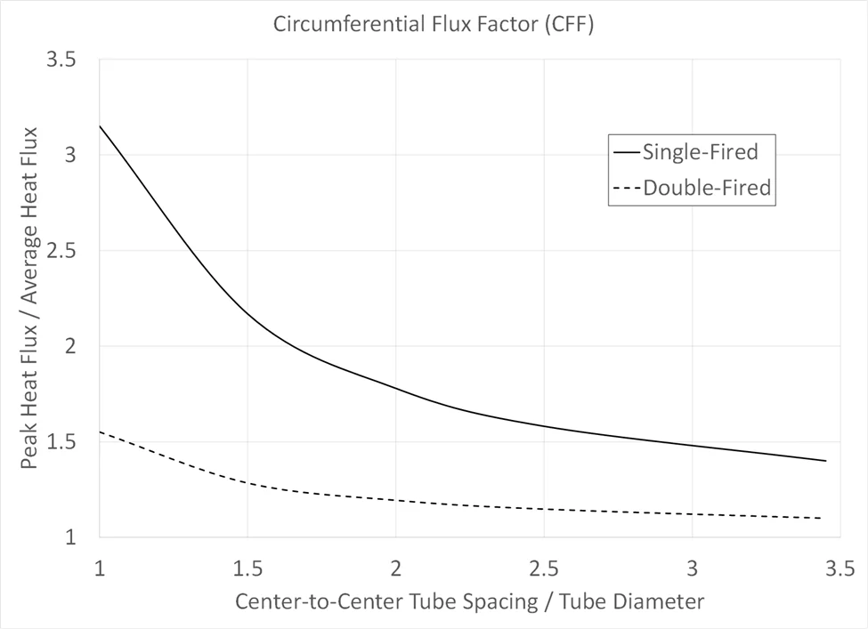
Figure 2 – Circumferential flux factor (CFF) for single-fired and double-fired tubes and various spacing.
The burners in fired heaters often produce flames from which the radiation varies significantly from the idealized infinite plane used to derive the CFF. The reasons for this are many, but the most common cause is that the burner flame is distorted by the flue gas flow patterns within the fired heater. The flames are then either pushed into the tubes or into each other. When the flue gas pushes the flames to the tubes, the local heat flux increases due to hot flue gas impinging directly onlto the coil surface. Alternately, the flue gas pushes the burner flames into each other and the fuel and air can no longer mix as designed. Instead, the flames become long resulting in a reduced radiant section heat transfer or the extreme case of flame impingement on the shock tubes at the entry to the convection section.
To calculate the heat transfer to the tubes, the degree of maldistribution within the radiant section that is not attributable to the CFF can be represented by a second factor, the Longitudinal Flux Factor (LFF). Figure 3 shows an example computational fluid dynamics (CFD) simulation where the flames impinge on the radiant coil. In this case, the CFD calculated CFF is 1.85 and the LFF for this case is 1.12, resulting in a combined peak-to-average heat flux ratio of 2.07. The combined peak value is critical because it sets the limiting tube metal temperature for the entire coil design.
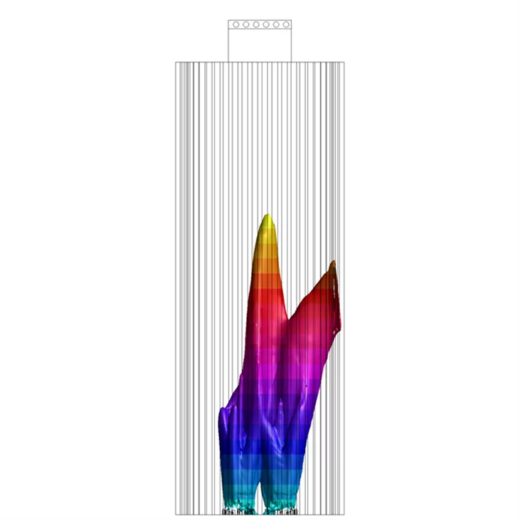
Figure 3 – Elevation plotted against a flame surface inside a vertical cylindrical heater.
Figure 4 shows the normalized heat flux within the radiant section versus elevation. As expected, 50% of the heat flux is greater than the mean. However, the extent to which the flux is locally greater than the average represents an opportunity to reduce tube wall temperature and increase coil utilization. A reduction of the LFF to 1.00 results in more of the coil surface being available for heat transfer, up to the CFF limit of 1.85. Reducing the CFF allows higher heat transfer to even more of the coil surface without exceeding the maximum tube metal temperature or film temperature of the process. Figure 4 shows that if the heat transfer is shifted from the 1.9 m to 4.9 m elevation to the 0.0 m to 1.9 m, 4.9 m to 6.1 m, and 8 m to 9.2 m elevations, the peak tube metal temperature can be reduced while maintaining or even increasing the heat input.
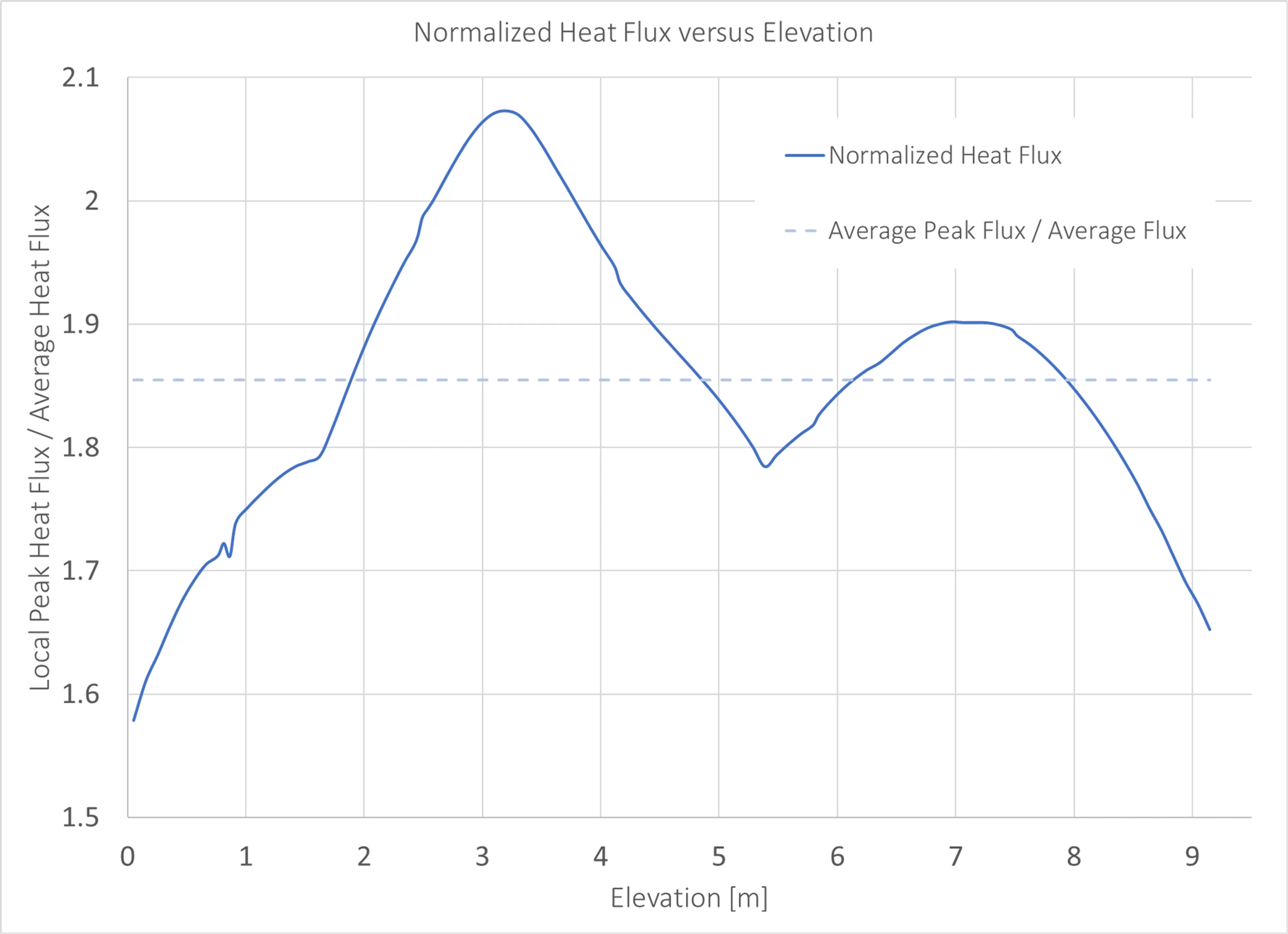
Figure 4 – The normalized heat flux from the CFD simulation.
Increasing Efficiency to Reduce CO2 Emissions and Fuel Costs
Additional recovered heat is often used to preheat the combustion air. Every unit of energy added to the combustion air is a unit of energy not needed from the fuel gas. Preheating the combustion air reduces fuel consumption and carbon dioxide emissions. When using purchased gas, the savings from reduced fuel consumption can be significant. One downside to preheated combustion air is the increased system complexity and maintenance requirements. The other major downside is that preheating the combustion air increases the NOx emissions from the burner flames.
Figure 5 shows the change in CO2 emissions and NOx when increasing efficiency by increasing the combustion air temperature. The baseline efficiency is assumed to be 80% while firing methane with 15% excess air. When increasing efficiency from 80% to 95%, CO2 emissions are reduced by 16%. However, due to the exponential dependence of thermal NOx production on temperature, NOx increases by 213% with the same change in combustion air temperature. For heaters operating near the permitted NOx limit, the available efficiency increase is limited by NOx emissions rather than heat transfer.
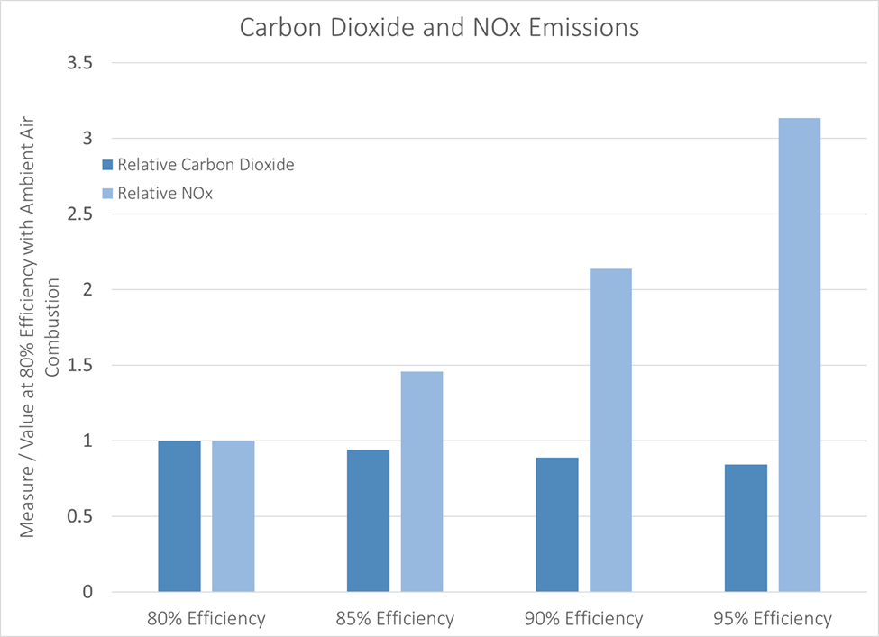
Figure 5 – Relative carbon dioxide and NOx emissions at various efficiencies gained by combustion air preheating.
An increase in efficiency using combustion air preheating does not necessarily lead to an increase in the available heater capacity. Increasing the firing rate of burners in conjunction with air temperature can still result in increased LFF and a tube metal temperature exceeding the maximum allowable temperature.
Using Hydrogen Fuel to Reduce CO2 Emissions
Burning fuels that do not contain carbon (like hydrogen and ammonia) eliminates carbon dioxide emissions. Hydrogen currently receives more industry interest because burning ammonia is difficult and produces large amounts of NOx. Potential issues for refueling existing heaters with hydrogen include:
- Burners that work well with 100% hydrogen generally do not work well with other fuel gases (which would be a problem if there is a hydrogen supply shortage).
- Air control can be difficult because of the reduced airflow requirement.
- Required fuel supply pressure is increased.
- Increased flame speed can lead to damage to the burners and heater.
- Material incompatibility with hydrogen combustion is likely.
- A reduction in the volume of flue gas through the convection section leads to reduced convection section efficiency
- Non-uniform increased radiant section efficiency from changing flue gas temperature, emissivity and volume may increase tube metal temperature beyond limits.
- NOx production is increased from the higher adiabatic flame temperature.
There are solutions to these issues, but they come at a cost. The most difficult problems are usually the increase in non-uniform heat transfer in the radiant section, which increases peak tube metal temperature, and the increase in NOx production. Figure 6 shows the change in normalized absolute scale tube metal temperature for different volumes of fuel hydrogen versus combustion air temperature. If only a burner replacement is considered when refueling with hydrogen, more than a 1% increase in absolute tube metal temperature is expected. Since many heaters already operate at or near the design tube metal temperature, this increase could be unacceptable.
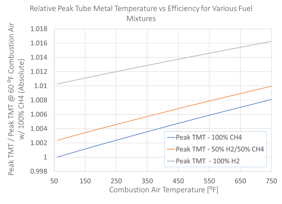
Figure 6 – Efficiency and normalized tube metal temperature for various mixtures of hydrogen and combustion air temperature.
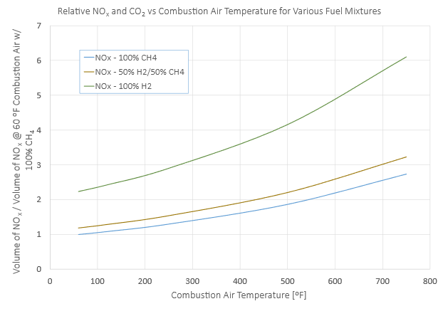
Figure 7 – Relative NOx for various hydrogen mixtures versus combustion air temperature.
Figure 7 shows the normalized NOx for various hydrogen mixtures compared to combustion air temperature. Different burners may produce data supporting a different relation, but all burners generally follow this trend. Most NOx produced in a burner flame is thermal NOx. Hydrogen has a higher adiabatic flame temperature than natural gas or refinery fuel, so the NOx will be higher, all else being equal. The regulated NOx limits most heaters have will not allow for increasing the NOx by such a large amount in trade for a reduction in CO2.
Prior Solutions for Increasing Efficiency, Increasing Capacity, Reducing NOx, and Reducing CO2
Rising fuel costs and CO2 penalties renew the drive to improve efficiency. Reduced capital inflows and unknown future operating conditions give increased importance to flexibility for existing heater capacity increases. Most heaters require a reduction in NOx or at least no increase in NOx given any other changes. Increasing efficiency and changing fuels are known methods to reduce the carbon dioxide emissions from fired heaters, but these require compromise.
Replacing conventional burners with low NOx burners and using preheated combustion air is a proven method to increase efficiency while maintaining or improving NOx performance. However, the NOx performance of low NOx burners has remained essentially unchanged for twenty years and the NOx emissions are generally too high when used with the highest efficiency – and therefore highest combustion air temperature – systems. An often-overlooked factor is that low NOx burners may change the LFF. Sometimes the long flames of a low NOx burner will reduce the LFF and, in turn, peak tube metal temperature. Often, long flames are instead moved by furnace currents towards the tubes which increases the LFF and causes unacceptably high tube metal temperatures. Regardless, no burner replacement can ever reduce the CFF, which will remain the limiting parameter in increasing the capacity of the heater.
When the NOx production from the burners is too high, an SCR may reduce NOx to acceptable levels, but the cost to install an SCR can be extremely high. Small heaters become very expensive on a cost-per-unit of NOx removed basis due to fixed engineering and project costs. Large heaters with a low process inlet temperature may require expensive modifications to the convection section to achieve the correct reaction temperature for the SCR catalyst. The installation of ammonia infrastructure and handling new chemicals may pose too great a burden to be worthwhile. And finally, because the SCR is a post-combustion treatment of the flue gas (neither the LFF nor the CFF is changed), any high tube metal temperatures caused by low NOx burners, hydrogen, or increased heater throughput are not addressed.
XceedTM: A Solution for NOx Reduction, Efficiency Improvement, and Capacity Increase
XRG Technologies developed the Xceed system for dispersed combustion in fired heaters to address the problems associated with changing fuels, increasing efficiency without increasing NOx, and improving the heat flux profile. The dispersed combustion provided by Xceed releases heat from the fuel without forming a flame. Xceed reduces emissions, provides more uniform heat flux, and allows for greater fuel flexibility.
The main elements and features of the system include:
- Air metered through burners (existing or new), enabling switching between conventional combustion and dispersed combustion from Xceed at any time
- Pre-conditioning of the fuel gas with flue gas externally to the combustion zone
- Injection of the fuel gas/flue gas mixture into the radiant section of the heater
- Specialized mixture nozzles that further enhance mixing and heat transfer
- Optional use of preheated combustion air to reduce CO2 emissions
This system works with burners in the fired heater. The combustion from fuel introduced by the Xceed nozzles proceeds without flame, reducing NOx and increasing temperature uniformity. The reduced NOx emissions enable efficiency improvement using preheated combustion air without exceeding NOx limits.
Figure 8 shows the Xceed system installed in a vertical cylindrical heater. Fuel is injected into the manifold which drives the flue gas from the point of injection upstream of the convection section through a manifold where the fuel and flue gas is premixed. This mixture is injected through specialized nozzles shown in the inset.
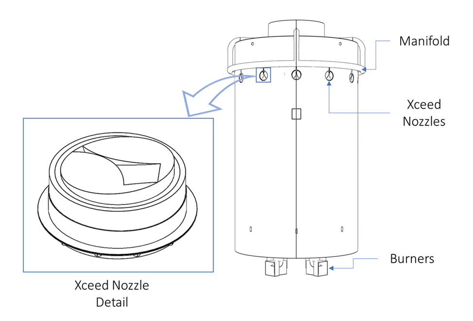
Figure 8 – The Xceed system installed in a vertical cylindrical heater.
Depending on the heater configuration, the benefits of Xceed can include:
- NOx emissions 3 times lower than low NOx burners
- A peak-to-average heat flux at the tubes 20% or less than conventional burners
- CFF reduced by 6% to 60% from the CFF taken from the API 560 reference curves
- Absorbed duty increase of 50% or more without exceeding the tube wall temperature limit or other component temperature limits
- Fuel efficiency improvement of up to 30% without increase in NOx emissions
Xceed Nozzle Design
The Xceed nozzle was designed to entrain more flue gas into the premixed stream of fuel gas and flue gas. Figure 13 shows the difference in performance for an Xceed nozzle compared to the typical simple high-pressure round jet. The new and unique geometry of the Xceed nozzle both entrains more flue gas and mixes it in a shorter distance. The shape of the nozzle removes the throat as a constraining dimension which is present in most nozzle designs. Using this optimized design, 1.6 times more flue gas is entrained within the same mixing length and the resultant mixture is more uniform. This reduces the potential for hot spots to form when the mixture encounters an oxidant.
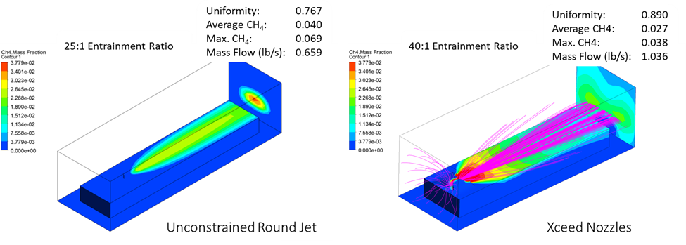
Figure 9 – An unconstrained round jet compared to the Xceed nozzle design.
Heat Flux Improvements
Figure 9 shows a significant improvement in peak-to-average flux ratio achieved by 95% of the heat release routed through Xceed. The CFD simulation results from firing a heater on natural draft using ambient air with low NOx burners compared to operating with 500 °F combustion air with Xceed, with 1.5 times greater absorbed duty. With Xceed, heat flux is 16% more uniform than using only burners and 6% more uniform than anticipated by CFF charts from API 530. This is equivalent to increasing the radiant section tube spacing by 15% without changing the coil in the heater.
This increased tube surface utilization in the radiant section increases heat transfer without increasing the peak tube wall temperature. The increase in heat transfer reduces the bridgewall temperature which further reduces the NOx produced by a heater with Xceed.

Figure 10 – Comparison of the peak to average flux ratio for ultra-low NOx burners and Xceed at 1.5x absorbed duty.
Tube Wall Temperature
Figure 10 shows a more uniform heat flux from operation with Xceed taken from a CFD simulation. This figure compares the normalized local tube metal temperature on the outlet tube from a heater operating with 500°F preheated combustion air with best-in-class burners and Xceed. When operating with Xceed, the tube is held at a higher temperature from 6 ft to 24 ft in elevation compared to the higher temperature region using burners which occurs from 24 ft to 40 ft. The peak temperature while using Xceed is still less than the peak temperature of ultra low NOx burners even though the absorbed duty is the same. In this case, the difference is equivalent to an 8°F reduction in peak tube metal temperature which is required to stay below the film temperature limit.
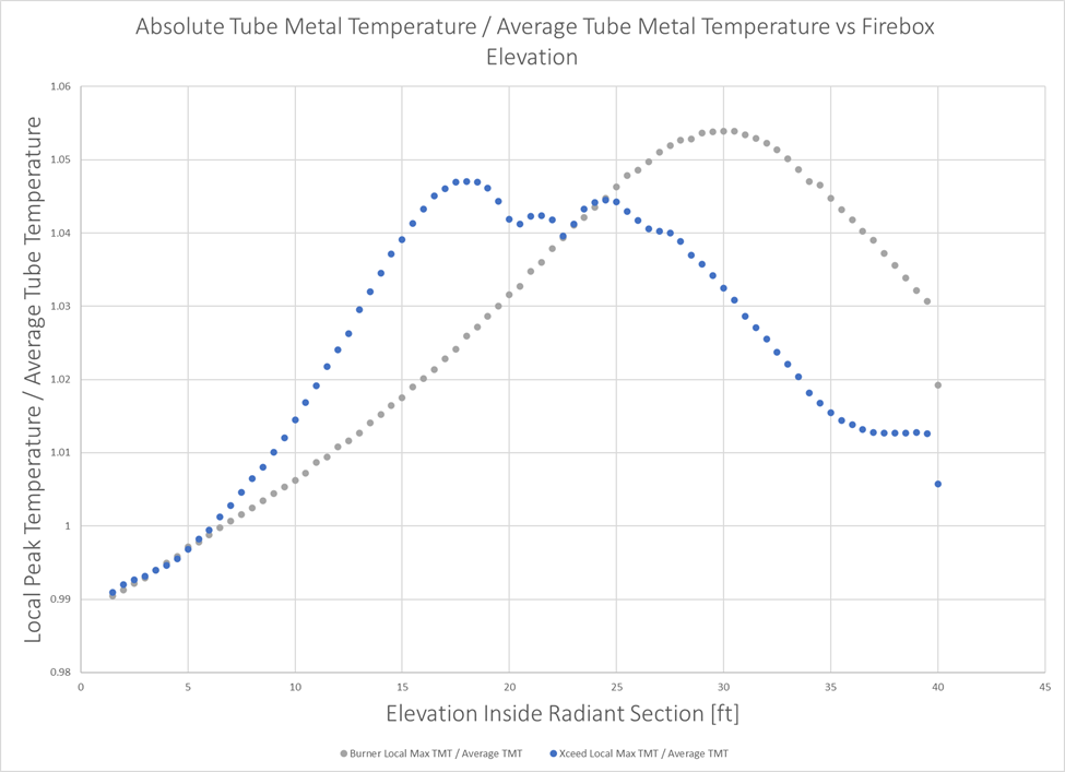
Figure 11 – Comparison of local peak tube metal temperature versus elevation for operation with burners and Xceed.
NOx Performance
Table 1 shows the NOx performance predicted by XRG Technologies’ proprietary CFD-based NOx model. A heater equipped with Xceed can operate with the entirety of the heat release coming from the burners or up to 100% of the heat release coming from the Xceed nozzles. For the simulated heater, the predicted NOx emissions are 28 ppm when operating with only burners. But, placing 50% of the heat release in Xceed nozzles reduces the NOx to 17 ppm. In the 95% Xceed case, all fuel aside from that in the pilots and a 5% baseload left in the burners, is diverted to the Xceed nozzles resulting in 9 ppm of NOx. Xceed works with all burners, but careful selection of the burners can result in superior performance. For the 95% Xceed with New Burners case (Figure 15), the resulting NOx is predicted to be 3 ppm.
Table 1 – CFD predicted NOx performance.
| Case | NOx [ppm] |
| 100% Ultra Low NOx Burners | 28 |
| 50% Utra Low NOx Burners / 50% Xceed | 17 |
| 100% Xceed | 9 |
| 100% Xceed w/ New Burners | 3 |
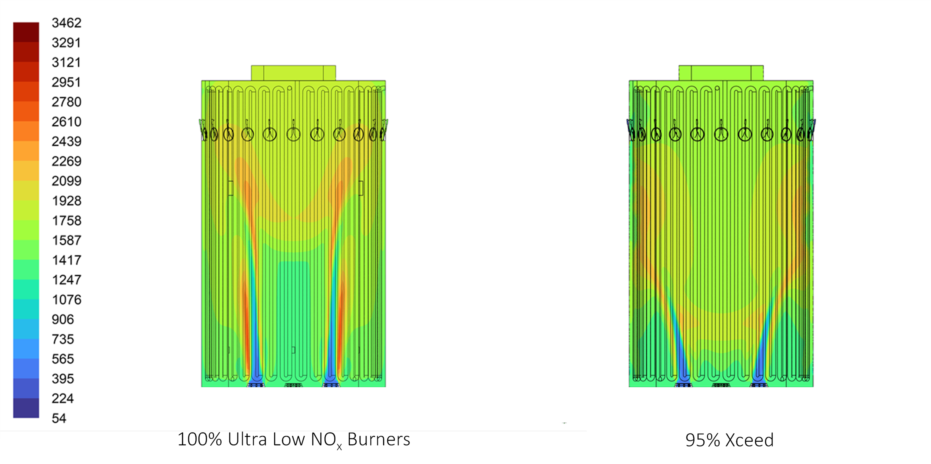
Figure 12 – Comparison of flue gas temperature [°F] inside the radiant section of a vertical cylindrical heater.
Figure 12 shows a comparison of the gas temperature inside the radiant section of the heater. The highest temperature region is 2800°F in the secondary stage flame away from the burners for the 100% Ultra Low NOx Burners case, while the highest combustion temperature away from the burners in the 95% Xceed case is 2300°F. By design, the 95% Xceed case increases flue gas temperature near the tubes but the peak flue gas temperature approaching the tubes remains at 2100°F or less. There is no flame in this region due to the low oxygen concentration and low temperature.
This relatively low dispersed temperature results in low NOx production. Figure 13 shows the reduced NOx production in the 95% Xceed case when compared to operation on ultra-low NOx burners. The combustion in the Xceed case still makes NOx at the boundary between the fuel/flue gas mixture and the air stream issuing through the burner but at much lower levels.
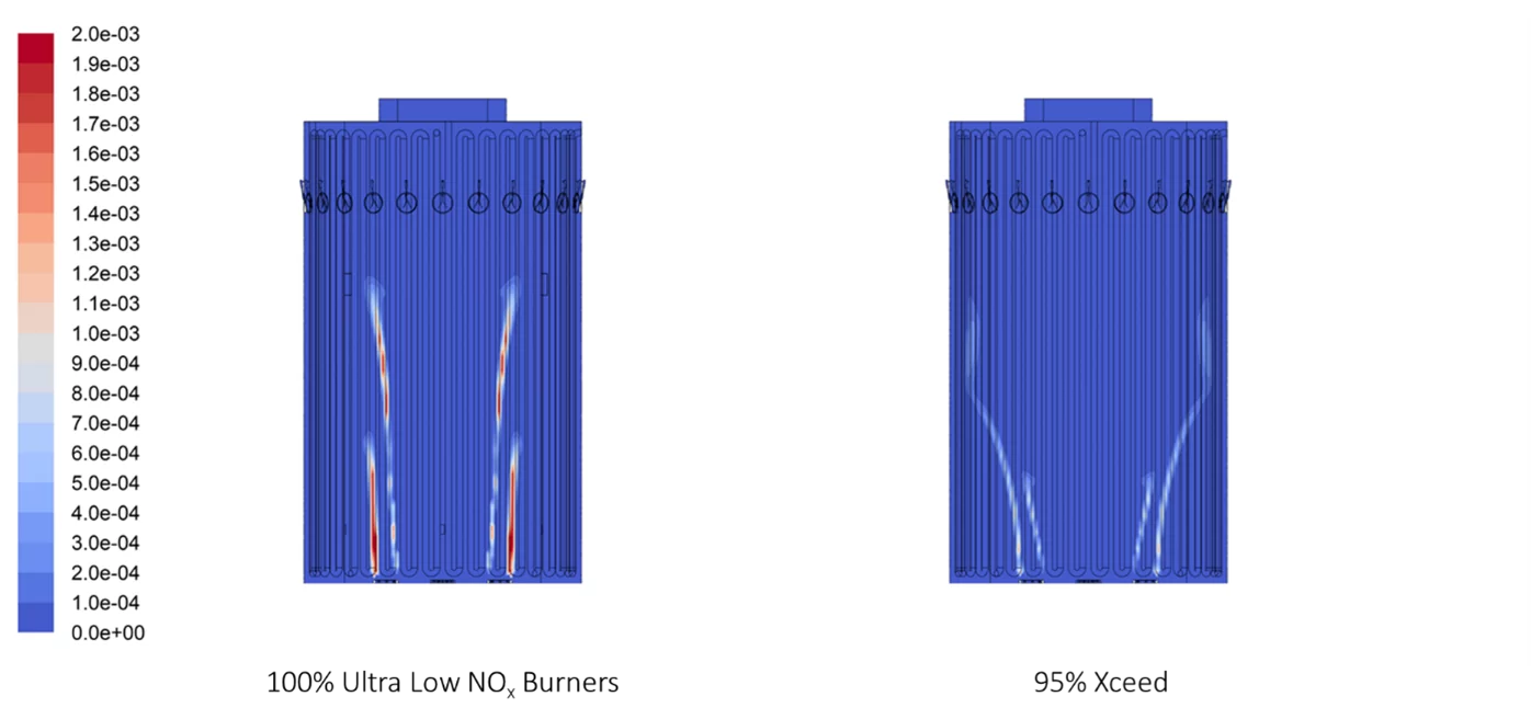
Figure 13 – NOx production [ppm/MMbtu] within the radiant section.
Performance with Hydrogen
Xceed preconditions the fuel before combustion and suppresses the peak temperature. Because the fuel is well mixed with a large volume of flue gas, the combustion proceeds mostly independent of the original fuel composition. Figure 14 shows the predicted tube wall temperature inside a vertical cylindrical heater operating with mixed fuel gas and pure hydrogen fuel. The increased mixing from the high hydrogen operation reduces the tube wall temperature instead of increasing the temperature as usually expected, but the absorbed duty is still increased. Changing from fuel gas to hydrogen did not increase NOx production—NOx production is predicted to be 17 ppm for both cases below.
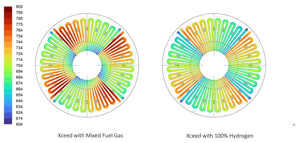
Figure 14 – Tube wall temperature [°F] inside a vertical cylindrical heater for Xceed using mixed fuel gas and hydrogen.
Impact of Air Leakage
Xceed extensively mixes fuel gas and flue gas to achieve dispersed combustion. Logically, this follows the composition of the flue gas that would impact temperature reduction and NOx performance. Simulations reveal that a realistic amount of leakage does not negatively impact the performance of Xceed – any local temperature rise due to increased oxygen from leakage is minimal because the combustible portion of the mixed stream is so diffuse. To test the impact of air leakage, several cases were simulated on a vertical cylindrical heater.
Figure 15 shows the tube metal temperature as a result of those simulations. The Base case shows the peak tube metal temperature is 805°F with 50% of the fired duty through Xceed and no leakage into the heater. The Burners Off case shows a temperature drop to 771°F with maximum burner airflow, but the only fuel flow comes from Xceed. The Leak at Seam case shows the peak tube metal temperature to be 767°F with a 0.125-inch gap at the top of the radiant section. The Sight Doors Open case shows the temperature reduced to 770°F when all the sight doors on the heater are open. Finally, the Explosion Door Leak case shows the temperature to be 771°F with a 0.25-inch leak around the periphery of the explosion doors. In no case does the air leakage increase the tube metal temperature when compared to a fully sealed heater.
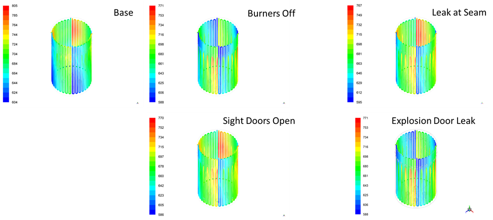
Figure 15 – Predicted tube metal temperature for various leakage scenarios.
Operation
The Xceed system is simple to operate because it uses existing burners. All startup, shutdown, and emergency shutdown controls and procedures remain the same. The Xceed nozzles are only permitted to operate when the temperature exceeds a minimum operating temperature that ensures complete combustion of both the fuel and any carbon monoxide. There is a rigorous and conservative method for calculating this temperature in the control logic. Because the fuel gas for Xceed is taken from the burner fuel piping downstream of the control valve, the temperature control loop for the process outlet temperature also remain unchanged. Figure 16 shows a simplified control diagram to operate the Xceed nozzles. This control loop is implemented independently of any current logic.
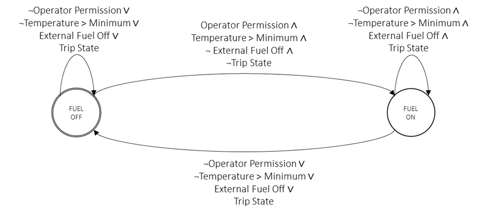
Figure 16 – The simple control scheme determining fuel flow to the Xceed nozzles.
Cost Savings
Table 2 illustrates the performance difference for a 100 MMBtu/h heater. Using a combustion air preheater increased fuel efficiency from 83% to 91%. Xceed can achieve this without using an SCR or paying for the installation of ammonia infrastructure to keep NOx emissions below permit levels.
Table 2 – Example performance for a 100 MMBtu/h heater.
| Measure | Base Case | Xceed Case |
| Fired Duty [MMBtu/h] | 100.0 | 91.2 |
| Fuel Efficiency [%] | 83 | 91 |
| Combustion Air Temperature [°F] | 60 | 500 |
| Carbon Dioxide Emissions [tonne/y] | 59,941 | 54,671 |
The reduction in carbon dioxide emissions corresponds to the reduction in firing rate. Savings from reduced fuel usage and carbon credits can be significant when using current and projected prices. Table 3 shows projected cost savings from projected carbon and fuel costs for the same hypothetical heater sampled for the EU. Using the assumed prices and a 365-day operating year results in approximately $2 million in savings every year for the next nine years. Regardless of future accuracy of the carbon and fuel costs, if the carbon credit price continues to rise and fuel prices remain elevated, savings could be significant.
Table 3 – Example of cost savings with efficiency improvements from Xceed.
| Year | Carbon Price [USD / tonne] |
Fuel Price [USD/MMBtu] |
Carbon Cost Savings [USD] |
Fuel Cost Savings [USD] |
Total Yearly Savings [USD] |
| Year 1 | 70.00 | 30.00 | 368,867 | 2,310,330 | 2,679,197 |
| Year 2 | 74.13 | 28.42 | 390,604 | 2,188,652 | 2,579,256 |
| Year 3 | 78.25 | 26.84 | 412,341 | 2,066,975 | 2,479,316 |
| Year 4 | 82.38 | 25.26 | 434,077 | 1,945,298 | 2,379,375 |
| Year 5 | 86.50 | 23.68 | 455,814 | 1,823,620 | 2,279,435 |
| Year 6 | 90.63 | 22.10 | 477,551 | 1,701,943 | 2,179,494 |
| Year 7 | 94.75 | 20.52 | 499,288 | 1,580,265 | 2,079,553 |
| Year 8 | 98.88 | 18.94 | 521,025 | 1,458,588 | 1,979,613 |
| Year 9 | 103.00 | 17.37 | 542,762 | 1,337,559 | 1,880,321 |
Summary
Environmental, economic, and market forces require that fired heaters maintain or improve NOx emissions, are more energy-efficient, can potentially increase their capacity, and have a reduced carbon footprint. The Xceed system enables these improvements in both new and existing heaters by changing the combustion to produce low NOx, optimize heat transfer, and enable higher preheated combustion air temperature for improved fuel efficiency.
These improvements can reduce fuel consumption and carbon dioxide emissions for some heaters. Given current and projected fuel and carbon dioxide prices, savings can be substantial. The Xceed system enables highly efficient, low NOx performance without the installation of ammonia infrastructure or the ongoing expense of catalyst reloads for SCR systems.
References
Hottel, H. C. (1983). Flux Distribution around Tubes in the Radiant Section of Processing Furnaces. Industrial & Engineering Chemistry Fundamentals, 22, 153-163.
About the Author:

As the Lead Scientist at XRG, Matthew Martin has over 30 years of experience in the combustion industry. He specializes in CFD of fired equipment, including UOP platforming heaters, burners in process heaters, thermal oxidizers and flares with over 300 simulations of installed, field-proven equipment. Matt received a Bachelor of Science in Computer Science from the University of Tulsa. He has written numerous publications and is listed as inventor or co-inventor on 27 patents.
XRG Technologies is an innovative engineering and procurement firm specializing in fired equipment for the refining, petrochemical, and power markets. We collaborate with our partners to solve complex problems and manage projects from concept to completion.
Our staff of industry experts will partner with you and function as your outside engineering support team. Our team of fired heater, burner, boiler, flare, vapor recovery and thermal oxidizer experts create one centralized, go-to engineering firm for all your fired equipment needs!